

 Current position > News detail
『How Does a Flow Meter Work: Principles of Fluid Dynamics』Related information(flow rotameter|digital flow meter|balo meter|hydraulic flow meter|volumetric meter|positive displacement meter|pitot tube flow meter|displacement meter|cfm meter|variable area flow meter|inline flow meter|differential pressure flow meter|calibrated flow meter|velocity meter|paddle wheel flow meter|oval gear flow meter|anemometer hvac|multiphase flow meter|doppler flow meter|thorpe tube flowmeter|heat flow meter)
How Does a Flow Meter Work: Principles of Fluid Dynamics
Quick Answer: A flow meter measures how much liquid, gas, or steam moves through a pipe per unit of time. It does this by sensing velocity, mass, or volume and converting that reading into a signal such as 4-20 mA HART or pulse. The exact working principle depends on the meter type — electromagnetic, Coriolis, ultrasonic, vortex, or thermal — each suited to different fluids and pipe sizes from DN15 up to DN2000.
What a Flow Meter Actually Measures in a Pipe
In practical terms, a flow meter captures one of three things: volumetric flow rate, mass flow rate, or flow velocity. Volumetric flow is measured in m³/h or L/min, mass flow in kg/h or t/h, and velocity in m/s. Most industrial meters installed in countries like Australia, Indonesia, Saudi Arabia, or Nigeria output volumetric flow first. Some convert it to mass flow using temperature and pressure compensation. One exception is the Coriolis mass flow meter — it measures mass flow directly with no compensation needed.
Here is the thing. Many engineers forget that the fluid dynamics inside the pipe change the reading. If you have a single bend or a partially open valve five pipe diameters upstream, the velocity profile is no longer symmetrical. That throws off an electromagnetic or ultrasonic meter. This is why installation guidelines say you need straight pipe runs — 5D upstream and 3D downstream for an average meter, sometimes 10D or more for custody transfer systems.
Bernoulli, Reynolds Number, and Why They Still Matter
Flow metering sits on two pillars of fluid dynamics: Bernoulli’s principle and the Reynolds number. Bernoulli tells us that as the velocity of a fluid increases, its static pressure drops. Differential pressure flow meters like orifice plates or Venturi tubes use this directly. They create a constriction in the pipe, measure the pressure drop, and calculate flow. For a DN100 pipe carrying condensate at 120 °C and 10 bar, a DP meter might still be the cheapest option — though we rarely sell one when an electromagnetic meter can do the same job with less permanent pressure loss.
Reynolds number tells us if the flow is laminar, transitional, or turbulent. A low Re value — say below 2,300 — means the fluid moves in smooth layers. Most industrial flows are turbulent, typically Re above 10,000. Vortex flow meters need turbulent flow to generate a stable Kármán vortex street. A vortex meter on a line with Re under 10,000 may simply stop reading. We have seen this on customer sites many times: a plant in Thailand installed a vortex meter on a 50 mm fuel oil line that would slow to a crawl at night when demand dropped. The meter underread by 15% until we upsized it to a thermal mass flow meter for low flow sensitivity.
How Each Meter Type Uses Fluid Dynamics
An electromagnetic flow meter works on Faraday’s law. The fluid must have a minimum conductivity — typically 5 µS/cm for standard electrodes, 20 µS/cm for a reliable 0.5% accuracy over the full range. This makes it perfect for raw water, wastewater, slurries, and any water-based chemical. It will not work on deionized water below 1 µS/cm unless you pick a specialized version with a high-impedance amplifier. For a desalination plant in Oman, we supplied electromagnetic meters on the brine discharge line, sized DN150 with PTFE liners and Hastelloy electrodes, talking Modbus RTU to the plant PLC.
A Coriolis mass flow meter directly measures mass flow by detecting the phase shift between two vibrating tubes. The fluid inertia creates a twist that is proportional to kg/h. This sensor does not care about density changes, conductivity, or Reynolds number within a wide range. A paint manufacturer in Vietnam uses our Silver Instruments Coriolis meter on a solvent blending skid, running at 50 cP viscosity. They dose resins and solvents in a batch process where 1% overfeed ruins the viscosity target. The meter gives them ±0.2% mass flow accuracy and also outputs density — two parameters from one device.
Ultrasonic flow meters come in two flavors: transit-time and Doppler. Transit-time meters send an acoustic pulse upstream and downstream through the fluid. The difference in travel time gives the flow velocity. Doppler meters bounce sound off particles or bubbles. For clean water, transit-time is the standard — clamp-on models can be mounted on the outside of an existing DN200 steel pipe without cutting. We did this for a municipal water supply authority in the Philippines that could not shut down the line. They gave us pipe material, diameter, wall thickness, and fluid temperature; we provided a clamp-on meter with a claimed accuracy of ±1% of reading.
Vortex flow meters rely on the Kármán effect. A bluff body in the flow stream sheds alternating vortices at a frequency proportional to velocity. They need a minimum straight run of 15D upstream and 5D downstream if placed after a valve. They work well on saturated steam, compressed air, and natural gas applications where temperature is stable. A food processing facility in Mexico uses our vortex meter on
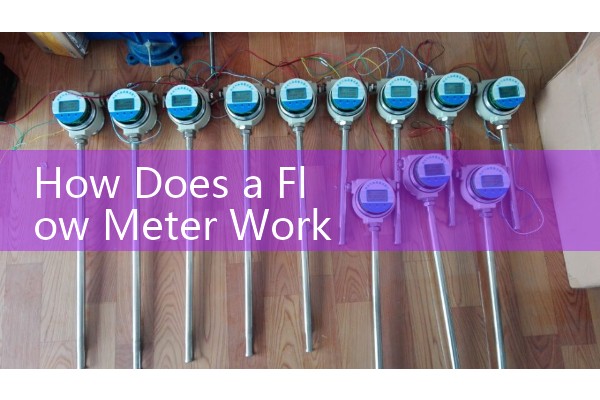
Thermal mass flow meters operate on the principle of heat dissipation. Two RTDs (typically PT100 sensors) sit in the gas stream — one heated, one at gas temperature. As flow increases, more heat is carried away. The differential temperature translates to mass flow directly. They are ideal for aeration air in wastewater plants, biogas with methane content measurement, or nitrogen purge lines. An LNG terminal in Qatar uses our thermal meter on a nitrogen blanketing header to detect low flow, triggering an alarm if the purge drops below 10 Nm³/h.
Oval gear positive displacement meters trap a known volume of fluid between two rotating gears and count the revolutions. Every pocket of liquid equals a fixed volume — maybe 100 mL per pocket. They excel on high-viscosity liquids like heavy fuel oil, diesel, palm oil, or glucose syrup. A biodiesel trader in Brazil uses our oval gear meter on a filling skid for 1,000 L IBC totes, where repeatability of 0.1% matters more than absolute accuracy.
Signal Output and Real-World Integration
Most engineers skip this part until it is too late. The fluid dynamics are only half the story. You need a signal that the control system can read. For a typical procurement in Southeast Asia, the buyer wants a flow meter with a 4-20 mA analog output, maybe HART protocol on top for remote configuration. Pulse output is common for totalizing, with a frequency of 0 to 1,000 Hz. In hazardous areas, say an ATEX Zone 1 gas environment like a refinery in Saudi Arabia, the flow meter must have Ex certification and often uses an intrinsically safe 4-20 mA loop.
A customer in India asked us last month: “Should I get fieldbus?” It depends. Profibus PA and Foundation Fieldbus are less common now in SME plants. The simpler path is 4-20 mA HART into a local PLC, then Modbus RTU or TCP/IP to the SCADA. For standalone installations with no PLC, we sometimes supply a flow meter with a built-in digital display and a battery-powered totalizer — like our electromagnetic meter with an onboard register for a remote borehole in outback Australia.
Installation Factors That Change Accuracy
Because fluid dynamics is sensitive, small details in mounting create real errors. A vertical pipe with downward flow can cause the pipe to run partially full, making an electromagnetic meter report flow that does not exist. A temperature stratification after a heat exchanger can mess up ultrasonic transit-time readings. A low-conductivity fluid that just barely meets the meter minimum can drift by 2% between summer and winter due to water source changes. We learned this working with a chemical plant in South Africa switching between municipal water and dam water seasonally — the dam water had lower conductivity and the meter needed a calibration offset.
Grounding is a practical issue for electromagnetic flow meters. You must ground the fluid to the meter body, or use grounding rings on non-conductive liners. Without it, stray currents from nearby VFD motor drives inject noise into the signal, and the reading fluctuates widely. For a 40 mm meter on PVC pipe, always install a grounding electrode or ring upstream. In metallic pipe, a simple connection to the adjacent flange bolts often works.
Choosing a Flow Meter: Fluid Data You Need to Send Us
If you want a quote from Silver Automation Instruments, do not just tell us the flow range. Send us the fluid name, pressure (bar), temperature (°C), pipe size (DN), conductivity (µS/cm) for water-based fluids, viscosity (cP) for fuels and oils, and the required output signal. With those six parameters, we can pick a meter that matches your fluid dynamics reality, not just a datasheet ideal. For example, a customer in Kenya wanted a “water flow meter for a borehole.” After we asked for the conductivity, it turned out the water was 2 µS/cm — too low for a standard electromagnetic meter. We supplied a mechanical turbine meter, which cost less and worked fine on that clean groundwater.
FAQ
Q: Do I need straight pipe run for every flow meter type?
A: With Coriolis meters, very little. With ultrasonic clamp-on, 10D upstream is standard. Electromagnetic meters are more tolerant, 3–5D upstream is typical. Vortex meters demand the longest straight run — up to 30D if placed after a control valve.
Q: Can one flow meter measure both liquid and gas?
A: Not usually. An electromagnetic meter only works on conductive liquids. A Coriolis meter can measure both if the flow tube is designed for it, but most models are liquid-only. Thermal mass is gas-only. For mixed phase flow, contact us with full process details.
Q: What is the most common failure mode in a flow meter?
A: In our experience, it is installation error or process condition mismatch. The meter works on the test bench but sees an asymmetric velocity profile, air bubbles, or coating on the electrodes. That is why we always ask about upstream pipe layout and fluid char